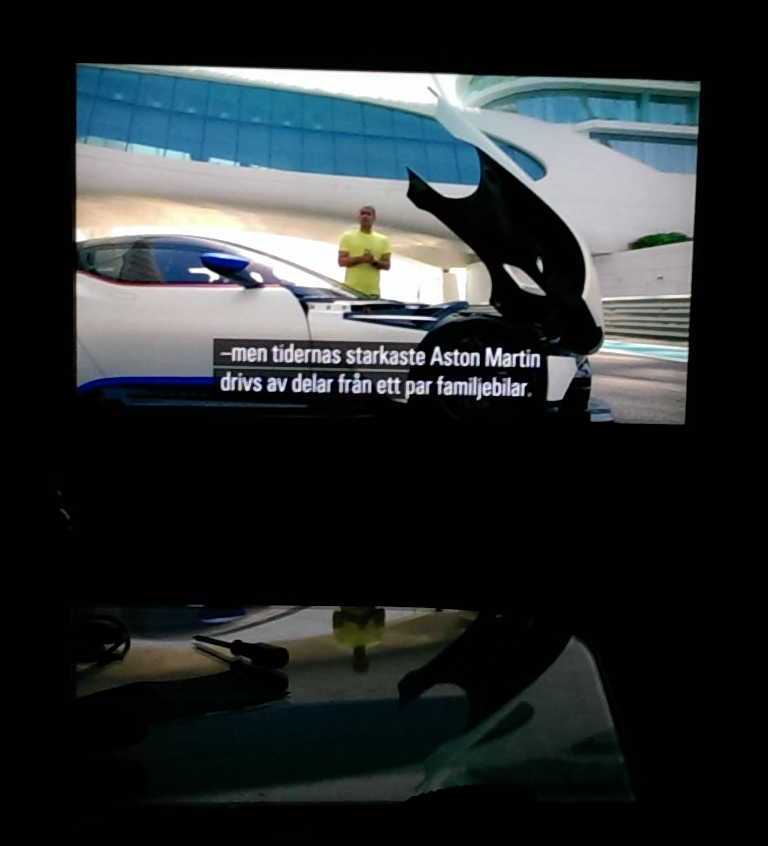
So here’s a followup on my last post (found here)! The chip arrived fairly quickly. Placed the order on tuesday night and I had it the next monday. I decided I needed some practice soldering first (don’t want to have the actual T-con board in my TV be that mess of black horror that my practice boards turned into), and so it took me a while until I had the courage to go for the real chip. Since I had trouble finding PCBs to practice on it took some extra time. Finally got it done yesterday, and well, it’s working! :D It’s actually working! I actually have some trouble believing it myself! Really happy though! Sorry about the crappy picture quality (taken with my phone from the sofa in a dark room).
This post will mostly be about the process of switching the chip!
So I came to the conclusion that the easiest way to remove the chip would be to use a heat gun. I could use something like Chip Quik too, but I don’t have any and it’s not really cheap either. But I do have access to a heat gun, so heat gun it is! Being a bit paranoid, I decided to cover up the surrounding areas with capton tape first. Just making sure I don’t blow resistors all over the board, and better safe than sorry.
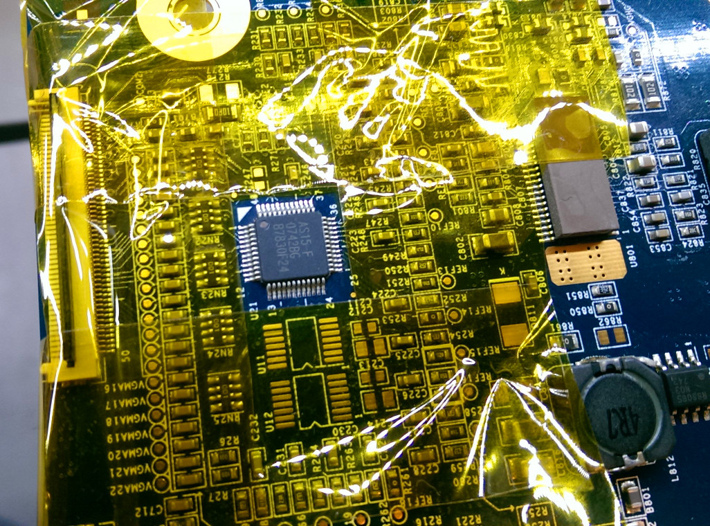
So I applied some flux for good measure, cranked up the heat on the heat gun and got to work! Tried to start with some sort of soaking phase for like a minute or so, letting the flux flow out properly before getting in close with the heat trying to melt that solder! Took me a fair bit longer than I would have liked, so I’m glad I went with that capton tape. Maybe that led me to becoming a bit careless too, because when the chip finally came off, probably my biggest fear in the world at the time came true, with me lifting two of the pads from the board. :( And I thought I was really careful! Can’t stress enough how important it is to not add any force to the chip. When the solder finally melts, you’ll be able to move it with the slightest nudge, and before that, you don’t want to move the chip as it will destroy the board!
I was a bit worried the board was done for at this point, but wasn’t going to give up easily! Here I’m so grateful that I have access to a really nice microscope, so that I could get in close and look at the damage. Luckily, the copper pads were still connected to the board, they had just lifted. So really carefully, while looking in the microscope I was able to get in with the soldering iron, melt some solder on the pads and get them back in a nice position. Amazingly it turned out really well, and I couldn’t even tell I had lifted them when I was done. Then there was just a slight cleanup with solder wick and some isopropanol, then carefully adding some new solder. Below picture is taken with my phone through the microscope, so conditions aren’t optimal. It looks much nicer looking through it with your eyes. You get tons of detail, and also thanks to the stereoscopic vision a sense of depth! I can’t stress enough how helpful it was to have a microscope. It would still be doable without it, but the confidence you get by seeing what you’re doing is invaluable!
![]()
So now I only needed to get the new chip in place! Since I already had the solder in place, I shouldn’t need any more, just lots and lots of flux (mm, flux fumes…). Get some good ventilation, or like me, open the window and turn on a fan! Trick was to get the chip in the perfect position and then tack it down into position by heating up one of the corner pins and its corresponding pad, reflowing the solder already on there to hold it in place. Then do the same to the opposite corner, and then it’s just a question of doing all the other pins too.
Easy in theory, but it still took me quite a few tries until I was really happy with all the joints. Trick is to properly heat up both pin, pad and get some really nice action in the flux all at the same time, then things will end up beautifully. Being relatively new to this, having the microscope was again soo nice, especially for inspection purposes, looking for shorts and so on, but with some more practice it should probably not be needed.
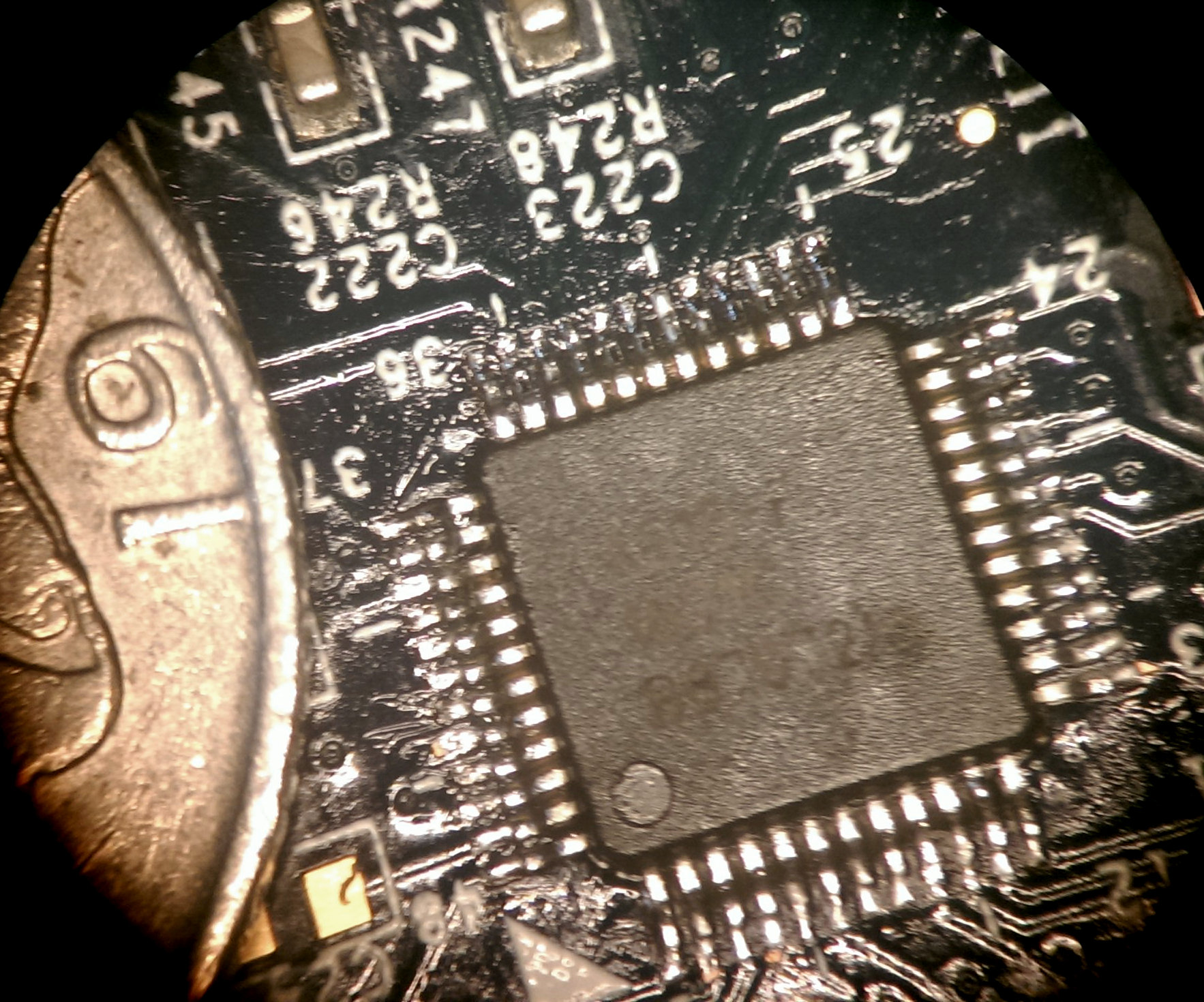
Anyway, after a while I was finally happy with the result. The chip wasn’t pitch perfect in position (to little for me to see with just my eyes however), but there was no risk of a bad connection or shorts. So here’s another crappy picture with the new chip in placce! :) With the edge of a swedish 1 kr coin for comparison, to give a sense of scale.
So yeah. After that it was just to put it back in place, connect all the wires and hope for no smoke! There was no smoke, and the picture was back. So me happy! And for the end, I’d just like to add some memorable words by Darth Vader: